- Your one stop shop for KNX devices in the USA 🇺🇸
- (+1) 786 956 6821
- support@knxsupply.com
- Store Location
- Sign in or Register
- Home
-
Categories
- System Devices
- Switching/Shutter Actuators
- Dimming Actuators
- HVAC
- Binary Inputs
- Keypads
- Gateways
- Enclosures and Boxes
- Occupancy Sensors
- Visualization Systems and Touch Panels
- Weather Sensors
- Drivers and ECGs
- Special Sensors
- HVAC
- Accessories
- Cable
- Expert Picks
- KNX Certified Training
- Newest Products
- Best Selling Products
Brands
- Articles
- Contact Us
- Home
- All Collections
- SIEMENS
SIEMENS
- Outputs: Eight outputs (latching relays, potential-free contacts)
- Electrical rating per output:ac/
- 347 Vac, 50/60 Hz, 15A , cos phi = 1
- 277 Vac, 50/60 Hz, 20A , cos phi = 1
- 1.5 HP @ 120 Vac
- 3 HP @ 277 Vac
- Control voltage: 1 to 10V (provided by ECG Dynamic ballast)
- Dimmable electronic ballast: Maximum 60 units
- Signal amplifier: Maximum 12 units
- Surface mounting box for presence detectors UP 258Dx1 AP 258E11
- For mounting presence detector UP 258Dx1 as a surface-mounted device.
- Color white (similar to RAL 9016)
- Dimensions (LxWxH) 109x109x30 mm
The Connect Box radically lowers the effort, investment, and complexity of integrating devices and equipment to a common system and retrofitting additional functionality to optimize the building:
- Plug and play installation and configuration experience optimized for installers such as electricians
- Library of over 500 field and equipment devices ready to connect
- Smart protocol gateway supports 11 communication protocols; both standard and proprietary, wired and wireless protocols including a local IoT private network based on LoRa
- Typically retrieves equipment data at 10-minutes intervals – adjustable by user per protocol and data point
- Powerful integration of third-party applications via public APIs, MQTT or Webhooks
- User web interface to remotely configure and provide optional, but important BMS functionality for selected licenses at https://connectbox.siemens.com
A software license is required to activate Connect Box.
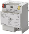
Input voltage
- Operation voltage: AC 110 - 277 V, 50...60Hz
- Rated power consumption approx. 3 W
Output voltage
- Rated voltage: DC 24 V (class 2)
- Safety extra low voltage (SELV)
- Permissible range: DC 21 ... 30 V
Output current
- Rated current 160 mA
- Short-circuit current: limited to 0.39 A
- The JB260C23 Binary Input is a KNX device with four binary input channels.
- The device is installed in a 4 x 4 inch junction box.
- The bus is connected via a bus terminal block.
- The device electronics are supplied via the bus voltage.
- The device enables recording of statuses (contact is opened or closed respectively voltage is applied or not) and changes in status (contact is being opened or closed respectively voltage is rising or falling), as well as voltage impulses.
- The JB512C23 Switching actuator (relay) is a KNX device with one switching output.
- The device is installed in a 4 x 4 inch junction box.
- The bus is connected via a bus terminal block.
- The actuator electronics are supplied via the bus voltage.
- The JB512C23 can switch resistive loads (e.g. electrical heaters, incandescent lamps, high voltage halogen lamps), inductive loads (e.g. motor, low voltage halogen lamps with intermediate conventional transformers), or capacitive loads (e.g. low voltage halogen lamps with intermediate electronic transformers).
- The JB513C23 Binary Output (relay) is a KNX device with three switching outputs. The device is installed in a 4 x4 inch junction box. The bus is connected via a bus terminal block.
- The actuator electronics are supplied via the bus voltage.
- The JB513C23 can switch resistive loads (e.g. electrical heaters, incandescent lamps, high voltage halogen lamps), inductive loads (e.g. motor, low voltage halogen lamps with intermediate conventional transformers), or capacitive loads (e.g. low voltage halogen lamps with intermediate electronic transformers).
- Each actuator output may be configured independently to provide switching, manual override, forced control, logical gate and status reporting.
- The JB520C23 solar protection actuator is a KNX device with one relay output.
- The device is installed in a 4 x 4 inch junction box.
- The bus is connected via a bus terminal block. The actuator electronics are supplied via the bus voltage.
- The JB520C23 may be used to control blinds, shutters, awnings, windows, or doors.
- The device is designed to drive (per channel) one AC 120V drive (motor) with electromechanical limit switches or with integrated electronics for disconnection at the limit positions.
- Their travel times must be manually measured as precisely as possible and configured in the application program.
- Parallel operation of several drives on one channel requires using a special separation relay. If such a separation relay is connected to the output to drive several drives in parallel, then the travel time must be configured manually.
- If the device is configured for automatic detection of the travel time, then parallel operation of several drives with electromechanical limit switches or mixed operation with drives with integrated electronics for disconnection at the limit positions is not permitted.
- Output for switching and dimming resistive, inductive or capacitive loads
- Automatic adjustment to leading edge or trailing edge control, depending on the type of load
- Rated frequency 50...60 Hz
- Electronic protection of the output against overload, short circuit and temperature rise
- Bus-powered electronics
- Integrated bus coupling unit, Bus connection via bus terminal block
- Type of protection: IP 20
- Rated operational voltage AC 120 V
- Protruding wires stranded AWG 12
- A phase connection for an output that is equipped with a relay contact per output as a switching element
- Contact rated operational voltage AC 120 V, AC 230 V, AC 277 V, AC 347 V
- Contact rated operational voltage AC/DC 24 V
- Contact rated current according to DIN EN 60669-1: 16 A / 20 A (resistive load)
- Fluorescent lamp load according to DIN EN 60669-1: 16 AX / 20 AX (200 µF) at AC 230 V
- Bus-powered electronics
- Integrated bus coupling unit
- Bus connection via bus terminal
- The device can be configured with Desigo Room Automation commissioning tool (ABT) or with KNX Engineering Tool Software (ETS).
- Protruding wires stranded AWG 12
- A phase connection for an output that is equipped with a relay contact per output as a switching element
- Contact rated operational voltage AC120 V, AC 230 V, AC 277 V, AC 347 V
- Contact rated operational voltage AC / DC 24 V
- Contact rated current according to DIN EN 60669-1: 16 A / 20 A (resistive load)
- Fluorescent lamp load according to DIN EN 60669-1: 16 AX / 20 AX (200 µF) at AC 230 V
- Bus-powered electronics
- Integrated bus coupling unit
- Bus connection via bus terminal
- Red LED for display of the activation of the addressing mode as well as the operational readiness
- The device may be used for permanent interior installations in dry locations within distribution boards or small casings with DIN rail EN 60715-TH35.
- To ensure an uninterrupted power supply a separate circuit with safety separation should be used for the power supply unit power supply line.
- The KNX/DALI Gateway communicates with up to 64
- DALI actuators per channel. These can be connected and dimmed in up to 16 groups per channel.
- The gateway also supports selected sensors with DALI interface.
- It also records and transfers DALI status and error messages.
- An individual name, a group, parameter and scenes are assigned to individual DALI ECG´s during commissioning with the ETS (Engineering Tool Software).
- DALI sensors and their functionality are also assigned in the ETS.
- All DALI subscribers and functions are independent and can be linked via group addresses.
- The device can only be operated in DALI segments with connected ECGs and sensors and not with further DALI controllers within the segment (no multi-master mode).
- The power needed for ECGs and sensors is supplied directly through the gateway. An additional DALI power supply is not required, neither is it permitted.
The Siemens Industry Gamma Lighting Control Enclosures support Gamma Lighting system components and other panel-mounted devices that snap into DIN rails.
Specially designed to accommodate the different DIN rail-based KNX modules, regardless of the manufacturer.
The following table provides ordering information:
Description | Product Number |
| Gamma Lighting Control 20" (51 cm) Enclosure | LCC-2020-MV |
| Gamma Lighting Control 28" (71 cm) Enclosure | LCC-2028-MV |
| Gamma Lighting Control 44" (112 cm) Enclosure | LCC-2044-MV |
Enclosure Type: UL and cUL Certified NEMA Type 1 Industrial Control Enclosure
- The power supply of the electronics occurs via the connection to the primary line. This makes possible to detect and report a bus voltage failure at the secondary line.
- Used as a line coupler, it joins up the lines with the main line to create a function zone; as a backbone coupler, it joins up the function zones with the overriding backbone line.
- Both types of couplers link primary lines and secondary lines as governed by their filtering tables to only pass on group telegrams if their destination address is recorded in the filtering table.
- Used as a repeater the device enables the connection of more than 64 bus devices to one bus line.
- Up to three repeaters can be connected to one bus line (as shown in figure 1) thus enabling the connection of a total of 252 bus devices (additionally to the three repeaters) to one bus line.
- KNX/BACnet Gateway: Bridges communication between KNX and BACnet networks.
- 250 Communication Objects: Converts KNX group addresses into BACnet objects automatically.
- COV Subscriptions: Supports up to 455 real-time value subscriptions for efficient monitoring.
- Integrated Web Server: Offers a user-friendly interface for configuration and monitoring.
- Remote Parameterization: Includes a KNXnet/IP interface for remote access via ETS.
- Security Options: Features password protection and VPN support for secure network access.
- Flexible Power Supply: Operates with external SELV AC/DC 24V.
- DIN Rail Compatible: Easy to install on DIN rails for a compact setup.
The IP router has the following attributes:
- Easy to connect to higher-level systems by using the internet protocol (IP)
- Secure access and data transfer via KNXnet/IP Secure
- Direct access to the KNX installation from every point in the IP network (KNXnet/IP tunneling)
- Fast communication between KNX lines, areas and systems (KNXnet/IP routing)
- Communication across buildings and properties (networking properties)
- Filtering and forwarding of telegrams according to: Physical address, Group address
- LED displays for Operational readiness, KNX communication, IP communication
- Easy and secure configuration using ETS
- Easy to connect to visualization systems and facility management systems
- Slot for SD card (not in use)
IP Interface Secure has the following attributes:
- Easy to connect to higher-level systems by using the internet protocol (IP)
- Direct access to the KNX installation from every point in the IP network (KNXnet/IP tunneling)
- Up to five KNXnet/IP tunneling connections are possible at the same time
- LED displays for operational readiness, KNX communication and IP communication
- Easy and secure configuration using ETS
- Easy to connect to visualization systems and facility management systems
- Slot for SD card (not in use)


